
Output transformer (not shown) for a current boost, then from the output V2's output goes out the blue wire to the

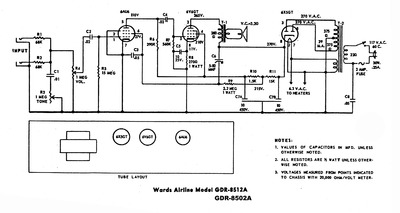
The audio signal goes back to the circuit board then down to the power tube V2įor the third stage of amplification. Second half of the first tube) for its second stage of amplification. The signal then goes up to the circuit boardĪnd on to the volume control at top center, then back down to tube V1B (the Upper right guitar Input Jack 1 or 2 and flows down to the circuit boardĪnd then to the preamp tube V1A at bottom right where the signal goes through Signal flow is shown above and below (orange arrows above, fat red line below). Will help you understand how this amp works. Tracing the signal path on this layout diagram and the schematic below

Power tube grid leak (R9) and the power tube cathode resistor (R8) and cathode bypassĬap (C6) to the first filter capacitor's ground (C3) is best practice and shouldĪnnotated Layout With Signal Flow and Component Function Questions about the grounding scheme shown in this layout. Compare this to the picture of the chassis above. I added component numbers to this layout that match the schematic diagramīelow. In" are the output transformer primary wires and "OT Out" are the secondaryĥF1 Champ Guitar Amplifier Layout Diagram The output transformer (OT) is not shown but "OT Is in the center, the power transformer (PT) is on the left and the tubes and The guitar input jacks are at the upper right, the circuit board If things get too cluttered youĬan refer back up to this clean diagram. We'll start with the amplifier layout diagram. High voltage then have an amp technician service your amp. If you have not been trained to work with Tube amplifier chassis contains lethal high voltage even when unplugged-sometimes Output Transformer are attached to the other side of the chassis.

V2 Power Tube in center, V3 Rectifier Tube on left. Volume control on top, Circuit Board inside, tubes on bottom: V1 Preamp Tube on right, Tube amplifiers too with the goal of distortion prevention in audio amps being the This page discusses Guitar tube amps everything here applies to audio stereo Understand the simple 5F1 you'll be able to understand more complicated amps.ĥF1 was Fender's internal model code for the 1950's tweed Champ. This very simple but great sounding 1950's Fender 5F1 Champ guitar amplifier. Wondered what all those parts do? Well, I'll walk you through the signal Have you ever looked at the guts of a guitar amplifier and How Tube Amplifiers Work The layman's guide to understanding electric guitars and


 0 kommentar(er)
